


The R-value on a batt pack describes an insulation product. The performance of the finished wall depends on the framing, installation and every other layer around it. Moisture adds another reason to assess the complete assembly.
The frame changes the result
Heat can pass through framing members as well as through the insulation between them. Steel is highly conductive, so thermal bridging can reduce the benefit of the installed batts. The scale of that effect depends on the wall construction, stud centres, etc; a single percentage does not describe every project.
A higher batt R-value may help, but it does not remove the conductive path through the frame. Total wall assessment needs to account for framing and the thermal-break detail, including the relevant horizontal members, bracing and junctions.
Condensation depends on temperature and moisture
Condensation can form when humid air encounters a surface below its dew point. Thermal bridges can create colder local surfaces in winter, increasing the risk where moisture reaches them. The direction of heat and vapour movement can change with climate, season and air-conditioning.
That means a thermally unbroken steel member is not automatically wet, and a thermal break cannot guarantee a dry wall. Moisture entry, air leakage, vapour control, indoor humidity and the ability of the construction to dry out, all need attention.
What moisture means for insulation
Water and persistent damp can compromise an insulated wall, but the outcome depends on the insulation material, how wet it becomes and whether it can dry. Do not apply a percentage loss to every damp batt or assume all products recover in the same way.
The practical goal is to keep insulation correctly fitted and protected from water accumulation, while providing a suitable drying path for the assembly. A vapour-permeable membrane is one part of that strategy, not a guarantee of moisture safety on its own.
Give each layer a clear job
Thermal breaks reduce conductive heat flow at the relevant framing interfaces. Membranes and air-control layers manage water and vapour movement. A correctly detailed cavity provides drainage and, where required, ventilation behind the cladding. These functions work together.
The NCC energy-efficiency and condensation provisions must be checked separately for the project’s classification, climate zone, applicable edition and jurisdiction. Cavity depth alone does not prove ventilation performance, and a product R-value does not prove compliance of the complete wall.
A practical ATI detail
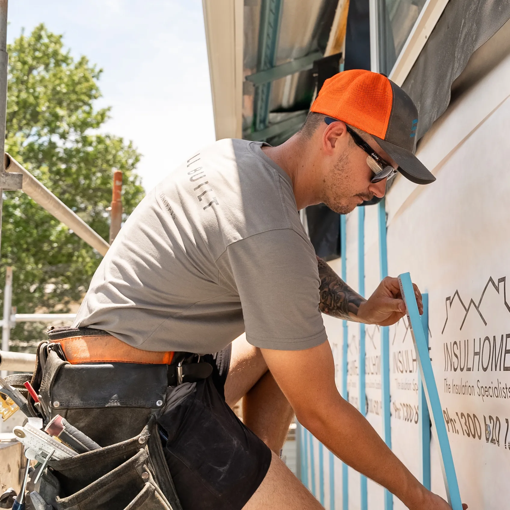
Cavi-Break® installs vertically over the wall wrap or membrane at framing members. Cavi-Vent® installs horizontally with integrated drainage and ventilation pathways. They are intended to combine thermal separation with cavity formation, subject to the project’s cladding and fixing details.
ATI’s X12 products have a nominal 12 mm thickness and published material R0.32; X20 products have a nominal 20 mm thickness and published material R0.58. Choose the configuration with the designer and assessor. These figures do not quantify the moisture performance of a wall or replace a condensation-risk assessment.
Compare the whole wall before changing the batts
A better thermal-break detail can improve the modelled wall result and may create flexibility in the insulation specification. The saving, if any, must come from a comparison of the same assembly and performance target. Do not reduce the batt specification on the basis of a generic example.
ATI’s published R-value comparison sheet reports a winter wall value of R2.2 for its modelled steel wall with 20 mm Cavi-Break and R2.0 batts. That example uses 90 × 35 mm steel studs at 600 mm centres, a 2700 mm wall height, 10 mm plasterboard, 9.5 mm fibre-cement cladding and the stated membrane. Different details can produce a different result.
Your next step
Start with the complete wall build-up. Use ATI’s Wall R-Value Calculator for an initial comparison, then have the project assessor verify the thermal result and the designer confirm the moisture strategy. Request the current technical pack and a sample so the intended detail is clear before installation.
General guidance only, not a project compliance determination. Confirm the applicable NCC edition and local variations, and obtain project-specific advice from the designer, energy assessor and certifier.
