


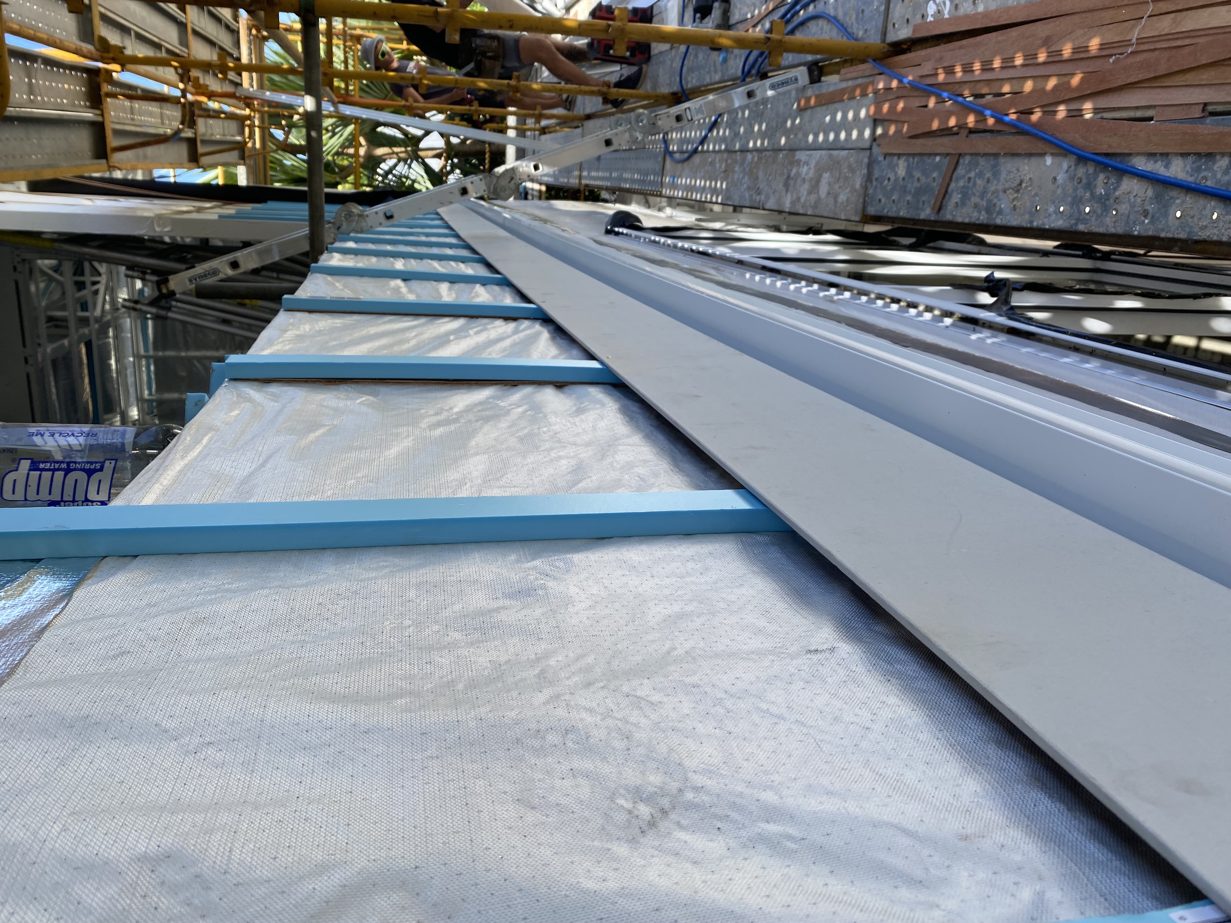
A suitable thermal break combines low thermal conductivity with the right installed thickness and location. For a steel-framed wall, the useful question is whether the product provides the required separation in the wall you are actually building.
Understand the requirement first
The NCC thermal-break provisions apply to defined wall constructions and compliance pathways. Where the relevant Housing Provisions requirement applies, the thermal break must provide at least R0.2 at the specified contacts between the metal framing and external cladding. In some situations, a horizontal secondary member is deemed not to require a separate thermal break. In these instances, the R value of the thermal break is not available and only the air gap R value can be claimed which is less than the minimum R value of a thermal break. Check the applicable edition, jurisdictional variations and wall configuration.
R0.2 describes the thermal resistance of the break. It is not the Total R-value of the wall, a condensation assessment or a fire rating. Each of those needs its own evidence.
Put the break in the heat path
Batts between studs insulate the spaces between framing members. They do not eliminate heat flow through the frame itself. A thermal break works by introducing resistance in that conductive path.
Check studs, plates, noggins, battens and junctions against the project detail. Do not assume that treating the vertical members only completes the job. The required continuity depends on where the cladding and framing would otherwise contact, as well as the construction covered by the provision.
If the energy assessment has been done using an accredited software, then the computer modelling assumes a thermal break is applied over all parts of the frame. Anything less means the ‘as built’ version will perform worse than ‘as modelled’.
Materials that may be suitable
Purpose-designed rigid insulating strips, suitable timber details and other low-conductivity products can provide thermal separation when their installed performance is supported by evidence. Material name alone is not enough: thickness, compression, durability, fixing arrangement and the intended use all matter.
For any installation, ask for the declared material R-value at the installed thickness, the supporting test or calculation, and the installation instructions. Check separately that the product is suitable for the cladding, loading, exposure and fire requirements of the assembly.
Treat air gaps and foil claims carefully
A drained and ventilated cavity has a moisture-management function. Do not assume that its nominal depth supplies the R0.2 material thermal break required at a cladding-to-frame contact. The treatment of an air layer in a thermal calculation depends on its geometry, ventilation and surface properties.
A foil-faced product also needs a more careful check than its headline R-value. Establish whether the quoted value belongs to the material itself or to a system that includes an adjacent air space. Compression at fixing points and the installed orientation can change the relevant performance.
Vapour control is a separate assessment. A reflective foil membrane does not necessarily create a blanket ban in climate zones 4 to 8, nor does it establish suitability. Check the product’s vapour-permeance classification, whether it is classed as a ‘water control layer’, its location in the wall and the applicable membrane requirements and exclusions.
Where Cavi-Break and Cavi-Vent fit
ATI’s Cavi-Break® and Cavi-Vent® are XPS thermal-break and cavity-batten products. Cavi-Break runs vertically over framing; Cavi-Vent runs horizontally with an integrated profile for drainage and ventilation.
ATI publishes R0.32 for the nominal 12 mm X12 products and R0.58 for the nominal 20 mm X20 products. These are material R-values, not whole-wall values. Select the thickness against both the thermal design and the cavity and fixing requirements, using the current technical documentation.
The product technical statement does not establish structural capacity, fire performance, an FRL or the suitability of a particular façade assembly. Those checks remain part of the project design.
Specify evidence as well as a product
Record the product, thickness, material R-value and installation detail in the specification. Keep the supporting documentation with the wall assessment so the intended performance can be checked on site.
Use ATI’s Wall R-Value Calculator to explore the assembly, then ask your assessor to confirm the inputs and compliance pathway. A sample can help the installer understand how the vertical and horizontal strips meet before work begins.
General guidance only, not a project compliance determination. Confirm the applicable NCC edition and local variations, and obtain project-specific advice from the designer, energy assessor and certifier.
